
Art Classes with Marc Surrency


Paper
This Section is Currently Under Construction
3. PAPER MAKING PROCESS
Once the wood has been reduced to pulp it is often made on a machine similar to a Fourdiner into a semi-paper form known as “wet-lap”, for shipping to, or transport around, the paper mill. The paper mill receives the wet-lap as rolls, bundles, or pallets of pulp sheets. The wet-lap usually requires additional refinement and treatment before being used to create the finished paper product.
3.1 FIBER SLUSHING, BEATING AND REFINING
The wet lap and any make-up materials, used in creating blends, must be mixed together, repulped, beaten and refined, before it is suitable for making paper. In rag paper, the wet-lap cottons, and linens are measured by weight and placed in a hydrapulper or digester with water, and “slushed” back into a pulp mixture. The digester disperses the fibers into the water with minimal fiber damage, by gentle agitation and heated water. After the wet-lap has been returned to pulp, it’s blown out of the digester and fed into a breaking engine.
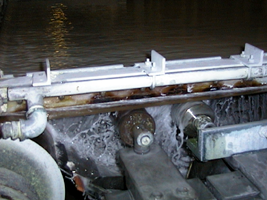
The breaking engine and Hollander are the same as discussed in section 2. The main purpose of beating engine (sometimes referred to as the “Bertram” after it’s manufacturer) is to further breakdown the pulp into separate fibers and filter out of any non-paper-making materials. The beater roll is kept well off of the bed plate and is gradually lowered ensuring that there are no sheaves (fiber bundles). After a short period of time in the breaking engine, the pulp is transferred to the Holland beater, where the fiber properties are further developed.
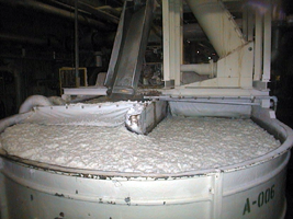
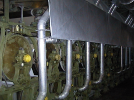
Bertram Beater refining the pulp
In the beater, the outer fiber wall is removed and the fiber’s cells are allowed to swell. At the same time the fiber length is adjusted by adjusting the distance between the blades on the drum and the blades or surface of the bed plate. As the drum revolves the blades collect fibers on the leading edge of the blade. As the rotating blades approach the stationary blades the fibers are either sheared or compressed between them, resulting in either frayed or shorter fibers. While the pulp is in the beater additives can be introduced to alter the properties of the finished paper. Some additives, such as clay (aluminum-silicate), Calcium carbonate or Titanium dioxide are introduced to increase opacity and increase brightness; dyes and pigments are added to adjust color and brightness, while Aluminum Sulfate activated rosin and Synthetic Alkaline resins are added for internal sizing. Internal sizing helps the paper to resist water and ink penetration.
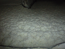
Pulp in the Bertram Beater
After the beater, the pulp is further manipulated by refiners. Refiners increase the bonding and surface areas of the fibers through a process known as fibrillation. Fibrillation is the fraying of the very fine, threadlike structures, called fibrils, that make up the fiber. The degree of fraying and the fiber length are determined in the same manner as the Hollander, by the type of blades used, the distance between them, and the time spent in the refiner. Two main types of refiners are used for this purpose, the conical refiner and the disk refiner.
The most common types of conical refiners are the Jordan and the Claflin. Both refiners consists of a stationary conical structure, lined with bars or blades running in the same direction as its axis, and a rotating cone structure called the “plug” which can be moved in or out of the stationary conical structure. The pulp enters the narrow end of the refiner and is forced out near the large end.
Disk Refiners can be used to further refine stock from a beating engine or in place of it. Disk refiners consist of at least two disk, that have bars or “ribs” across their faces. They are positioned face to face, so that one disk can rotate, while the other disk is stationary or rotated in the opposite direction. The refiner can be configured so that four disk are used instead of two, with two of the disk positioned back to back. The pulp enters either from the center and is discharged out through the perimeter, or enters through the perimeter and is discharged through the center.
Increase in refinement results in decreasing fiber length, increase in intra-fiber bond breaking (internal fibrillation), fiber end maceration (external fibrillation). These processes increase surface, bonding area, and fiber length continuity, which increase the fold, tensile and bursting strength, density, and retention of filler. The increase in refinement, decreases fiber length, which decreases the tearing strength and increases the paper’s sensitivity to humidity, changes resulting in paper curling and dimension change. Brightness and opacity are also adversely affected by higher levels of refinement.
Final Screening and Cleaning
3.2 HAND-MADE PRODUCTION
Hand-made paper making can be separated into two categories, professional manufacturing and amateur or artistic papermaking. Professional hand-made production represents the elite of the field. The finest paper available is produced by the professional hand-made process and requires the highest expertise and skill. The other category is composed of the amateur or professional artist who make paper from improvised or small operations, creating sheets for aesthetical purposes.
Professional hand-made production, although relatively slow, labor intensive, and expensive, produces the finest paper product available. Because of these reasons only the finest grades of linen and cotton are used. The “rags” are hand-sorted and pulped in small refining and breaking engines. After breaking and refining, the pulp is screened and pumped into head-boxes or stuff-chest, which in turn supply vats. Three craftsmen, two skilled and one lay, are tasked with forming the sheets of paper. The skills of the vatman and coucher determine the quality and consistency of the sheet. To form the paper the vatman uses a wooden frame, covered by a wire screen of either a “woven” or “laid” pattern, called the “mold,” and a deckle. The deckle keeps the paper pulp from flowing over the edges of the mold.
The exact method of forming paper varies with each vatman, but the basic operation is the same. The vatman holds the edges of the mold about arms length with the forming wire face up and the surface parallel to the surface of the pulp. The vatman then dips the front of the mold/deckle into the vat submerging approximately 3/4 of the mold/deckle. The vatman raises the mold/deckle and tilts it back towards himself than away causing a small ripple and evenly distributing the pulp as the water flows through the screen. He then produces a side to side tilting or shaking motion causing the settling fibers to orient themselves perpendicular to those already settled. The settling fibers are allowed to “set” and the excess water allowed to drain. The vatman is finished forming the sheet and places the mold/deckle at an angle for further draining. After a couple of minutes the coucher takes the drying mold/deckle flips and allows the other side to drain. The coucher takes the mold/deckle and, while holding it at an almost vertical angle, removes the deckle and places the mold face down onto a felt. The coucher then positions and places another felt on top of the drying paper sheet. The top felt must be placed with great care, any surface disturbance will ruin the paper. After a completed post (stack of sheets) has been formed, the “layman” or “layer” removes the post to the pressing room, where the post is placed into a hydraulic press and pressed with 100 to 150 tons of pressure, removing the excess water. The layman then removes the sheets and creates another sandwich of paper and felt, this time using felt board. This pile is placed in press, under slight pressure, overnight. This is called “exchanging” or “parting” and can be repeated depending on the type of finish desired.
Drying Sizing and finishing can be done by hand or by machine depending on the size of the operation and the size of the order. By hand the paper sheets are hung in drying lofts. Sizing by hand involves quickly and skillfully skimming sheets through a size vat without stretching the paper, or pooling the size. In another method sizing is performed by fanning out the sheets in a shallow tank, immersing, draining and pressing. There are also continuous feeding machines that submerge the sheets through a size vat and then presses and dries the sheets.
3.3 FOURDRINIER PAPER MACHINE
The majority of paper is manufactured on the Fourdrinier paper machine. Nicolas-Louis Robert developed his paper machine under the employment of paper maker Francois Didot and applied for its patent in 1798. Didot purchased the patent from Robert in payments, but fell behind following confrontations between the two. Robert took back his patent, but not before Didot had given the plans to his brother-in-law, John Gamble, who owned paper mill in England. Looking for investors, Gamble interested Henry and Sealy Fourdrinier in the development of the machine. Under the suggestion of Gamble, the Fourdrinier brothers employed Bryan Donkin to build and perfect the machine at the Frogmore mill, Two Waters, Hertfordshire, England. Because of a loophole in their patent, the Fourdrinier brothers, like Robert, never received royalties from their machine. But unlike Robert, who was financially backed by Didot, the Fourdrinier brothers ran into financial difficulty, due to lack of return on their investment. Although they never received any monetary recognition of their efforts the single forming wire machine carries their name.(hunter)
The Fourdrinier paper making machine is composed of three main sections: the forming section, the press section, and the dryer section. A Paper slurry consisting of around 0.5-1.0% fiber, is pumped into a box where it flows out through a slot onto a moving wire belt. Once on the belt the water is removed by draining and suction, leaving the fibers to form a very wet, and weak paper. The paper is then pressed, heated, dried, resulting in a continuous roll or “web” which can be further finished as desired or required.
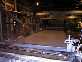
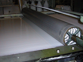
SIMPLE REPRESENTATION OF THE MODERN FOURDRINIER PAPER MACHINE
Wet end of a Fourdrinier paper machine. Head box is near the bottom. The drying section is towards the back .
3.3.1 FORMING SECTION
The forming section of the Fourdrinier constitutes what is called the wet end of the machine and is what the Fourdrinier brothers and their engineer, Donkin, perfected. This section consists of the head box, the forming wire, foils, suction boxes, couch roller, breast roller and dandy roll.
Pulp is pumped from the machine box through the screens and cleaners to the head box. The purpose of the head box is to deliver a uniform slurry to the forming wire. There are several different designs, but all incorporate a method to induce turbulence (deflocculation), while preventing cross currents, which would inhibit the uniformity of the stock. The simplest design is the gravity fed head box. It uses height/weight level difference to force the pulp through several baffles and a through a perforated rotating cylinder, before flowing through the apron and slice. A gravity-fed head box can deliver an eight-inch stock depth at a rate of 400 feet/minute.
If faster production speeds are required the stock must be fed under pressure. These machines can operate at speeds greater than 4,000 feet per minute. The pressurized head boxes are usually hydraulic and the stock is forced through conical injectors, through a perforated plate and through a horizontally split apron and the slice. The apron height and the slice height, which control the jet of pulp can be independently adjusted by hydraulics.
The pulp flowing onto the forming wire is approximately 0.5-1.0% fibers, with the make-up consisting of water. As the water is removed from the slurry, the fibers settle onto the surface of a traveling wire, forming a wet mat of paper. Therefore, the main objective of the forming section is the controlled removal of water. Originally gravity allowed the water to drain through a brass forming wire 60-70 mesh per inch, 40-50 feet length and 70-90 inches in width. But as production speeds increased, more efficient methods were developed.(Sindall) The forming wire, now a fine polymer screen with about 65 meshes per inch, carries the paper slurry over table rolls, foils and suction boxes, providing precise control over drainage and agitation control. As the slurry exits the slice onto the wire, the water starts draining from the suspension. Water jets are positioned over the edges of the forming wire to control the width of web, creating what’s called the deckle edge. The first fibers forming the mat on the wire are oriented in the direction of the machine; this is the wire side of the paper. If the rest of the fibers in the slurry were allowed to orient themselves in the same direction, the paper would have poor tear resistance and surface properties. If gravity was the main method of dehydration, the machine would have to be run at low speeds to overcome the orientation problem, the alternative is to remove the water quickly while the fibers are still agitated from the effects of the headbox.
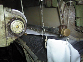
The first set of de-watering elements is a bank of table rolls. In earlier designs, table rolls were a series of small solid rollers. If they are used today, they much larger and are used as only the first water removal step. The rotation of the roll in contact with the covered wire causes a vacuum to form between the two, which pulls the water from the web.
Bank of table rolls removing the water from the pulp
With increasing speeds the table rolls cause problems with paper uniformity and aren’t able to remove enough water before the presses. Foils have replaced most, if not all of the table rolls. Foils remove water using a doctor blade on the bottom of the forming wire. The blade causes a difference in pressures, which draws water from the web behind the blade. This method allows for more control over the removal process and is not significantly affected by machine speeds.
Water removal can be further enhanced by placing a vacuum on the foil drainage system. The foil is essentially the same as that diagrammed above with the addition of vacuum pumps. After the foils, water is further removed using flat suction boxes. The suction boxes remove the majority of the water, changing the stock consistency from 2% to 20% fiber content. Above the first couple of suction boxes a skeleton roll covered with wire may ride on the top of the paper mat. This roll called a “dandy roll” compresses the paper, releasing any trapped air and improving the surface. The dandy roll can be covered with various wire patterns, which may simulate the forming wire and may have recessed or raised elements-designs imparting a watermark onto the paper. In areas where the watermark elements, usually a wire design, are above the surface of the dandy roll, fewer fibers are allowed to settle, and the paper appears light. If the watermark elements are below the dandy roll surface, more fibers are allowed to settle than in the rest of the paper, and the paper appears darker in these areas.
Dandy Roll
An alternative to using a dandy roll to create watermarks is the Molette. The Molette is a rubber stamp roll located before the wet press of the machine. This type of watermark actually embosses the paper and squeezes the fibers to the edges of the stamp.
3.4 TWIN WIRE MACHINE
A variation on the Fourdrinier was developed in the 1960’s and employed the use of two forming wire, allowing the paper mat to be dried from both sides simultaneously.
3.4.1 FORMING SECTION
The First Twin Wire machines were constructed so that the headbox sprayed a vertical stream between the forming wires at the nip of twin breast rolls. The paper web was then further drawn vertically, while vacuum boxes operate from both sides. Newer designs returned to a horizontal feed system with both forming wires traveling horizontally and vacuum boxes drawing suction from below and above the web. Another variation is the use of a de-watering mat above the suction boxes on a Fourdrinier; this is referred to as a Hybrid Twin Wire Machine.
3.5 CYLINDER MOLD MACHINE
In 1809, in Hertfordshire, England, John Dickinson invented another mechanical method of manufacturing paper, the cylinder mold machine. Dickinson approached the problem in a slightly different way then Nicholas-Louis Robert. Instead of pouring fibers through the forming wire, his machine dipped the forming wire into a vat, much in the same manner as hand made paper. This allowed him to create water marks and four-sided deckled edges comparable to hand couched paper.
The modern cylinder mold machine, also known as “cylinder vat” or “mold made,” is used to make fine bond paper with shadowed watermarks, currency and security papers, art papers, extremely heavy stock, corrugated cardboards, and multi-ply papers.
3.5.1 FORMING CYLINDER
The key to the cylinder mold machine is the use of a cylinder wire covered by the forming wire (now called the cylinder blanket or cover), partially submerged in a vat full of pulp. As the cylinder rotates into the paper stock, the slurry flows onto the surface of the cylinder, and the water flows through the wire cover to the inside of the cylinder where it is discharged. The fiber mat that accumulates onto the cylinder surface is removed or “couched” by a traveling felt belt. This traveling felt “the cylinder felt” is sometimes referred to as the forming wire, even though the paper is already formed by the cylinder. If multiple layer paper is desired, several vats and cylinders can be placed in series with the paper web acting as the cylinder felt for the additional paper mat. There are two main cylinder vat designs, contraflow and direct flow; and the cylinder felt can be above or below the drying stock.
3.6 PRESS SECTION
After the paper has been partially dried while on the forming felts and wires, it still contains vast amounts of water which must be removed to stabilize and strengthen the paper. The first of these additional drying sections is the press section. The press section or “wet-press section” contains several drying felts and suction pick-up (vacuum) rolls, which remove water from the paper mat until it reaches about 50%. Although the paper web can support its own weight, carrier felts support the web, while at the same time removing water from the surface and directing it through a series of vacuum rollers. The transference of moisture from the web to the felt is enhanced by the nips (the contact points between the rollers) of the rollers, suction boxes, and rollers.
3.7 DRYER SECTION
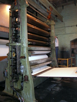
After passing through the press section, water is removed until the consistency of the web is about 5-12 % water. The removal of water is accomplished by a series of steam heated drums “dryer cans,” which evaporate most of the water from the web. The web is forced against the dryer cans by the dryer felt (a synthetic material that allows water vapor to pass through without absorption). As the water vapor leaves the dryer felt it is pushed away by forcing air across the felt. The dryer cans are usually around 4-5 foot in diameter and have highly polished shells.
Dryer Section
Another type of drying section utilizes a single large highly polished can instead of several smaller cans. This system, known as a Yankee dryer, is used with light grades of paper, like tissue.
3.8 FINISHING
After the drying section, the web is subjected to several finishing steps prior to shipping it as a final product. The web can be sized, giving the paper surface resistance, or if other properties are needed, the web can be surface coated. The web can also be supercalendered giving the surface a very smooth the uniform surface. In the final stages the web is rewound and slit into two or more rolls and if needed sheeted.
3.8.1 SIZING
Sizing imparts resistance to liquids on the paper surface, a property necessary for paper used for writing or printing. Without external sizing, ink would bleed and feather. External or Surface sizing can either be performed on the paper machine or on a stand alone unit.
Machine sizing can be performed either by running the web through a size vat or by running the web through a size press. In the case of the size vat, the web, after exiting the dryer section, is directed down into a vat and through another set of drying cans. Size presses are located after the between two dryer sections and applies a coat of sizing by transference from rollers and the metering is accomplished by the nip.
The most common types of sizing consist of pigments and starches, although animal glue and glycerin can also be used (art and banknote papers).
Spray sizing (starch) applied to the paper
3.8.2 COATING
Coating paper may be desirable or necessary to improve optical, printing/writing, and/or functional properties. Functional properties can be for protection form liquids, oils, gases, chemicals, improve adhesion characteristics, improve wear, or some other property.
Coatings can be classified as aqueous, solvent, high solids, or extrusion, coatings. Aqueous coatings, used for commodity papers, contain water soluble binders and are applied as a liquid. Common aqueous binders are Casein, Starch, Protein, Acrylics and Polyvinyl Acetates. Solvent Coatings are used in situations where the binders aren’t soluble in water and are used with specialty papers. High solid and Extrusion coatings are used for specialized papers, where chemical, gas or liquid resistance is necessary. High solid coatings are applied as a coating of monomers and are polymerized by UV or electron curing. Extrusion coatings are applied as a molten film of wax or polymer.
3.8.3 SUPER CALENDERING, COCKLING, AND EMBOSSING
After the chemical processes have been completed, physical processes, like super calendering, cockling, and embossing, can be used to create the desired surface texture to the paper.
Super calendering uses friction and pressure to create a very smooth and glossy paper surface. The super calender consists of a stack of rollers having surfaces alternating between steel and cotton in construction. There is enough pressure between the steel and cotton rollers to slightly compress the cotton surface causing a drag. The difference in surface speed on either side of the nip creates friction, which polishes the paper surface.
Calendering Rolls
The cockle finish on many bond writing papers is created by vat sizing the web then subjecting it to high velocity air dryers under high tension, then under low tension. The finished paper is usually heavily sized and has the characteristic rattle associated with high quality bond paper.
Embossing is achieved by running the web through an off-line press, where it is subjected to an engraved cylinder. The concept is similar to the dandyroll, but since the paper fibers cannot be redistributed the surface of the paper is raised or depressed.
3.8.4 SLITTING, SHEETING, AND SHIPPING
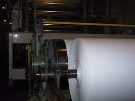
Once the paper roll (machine log) is reeled from the paper machine it is removed and transferred to a rereeler or a machine winder. A rereeler unreels the web from the mandrels to create a full log. During this process any defects can be removed and the web spliced. A machine winder is similar to the rereeler, but is able to slit the web into multiple, narrower rolls. These rolls can be further finished by supercalendering, embossing, etc., sheeted, or wrapped and shipped.
Paper roll at the winder
If the finished product is sheeted paper, the rewound rolls are transferred to machines known as cutters. The cutters can slit the web to form multiple narrower webs and cut across the web creating sheets. The paper rolls are placed onto a stand at one end of the machine. As the web unwinds it can be slit either adjusting the web width or creating several parallel webs. After the slitters, the web travels under a revolving knife, which cuts the web into sheets. After being cut the sheets are jogged through an on-line inspection system which checks caliper and dimensions. If the sheet does not conform it drops down into a sheeter for recycling as broke. After the cutters, the paper stacks are placed into guillotine trimmers, where the edges receive their final trim.
After trimming, paper rolls have inner headers (circular disks) applied to the ends, are wrapped with a heavy moisture resistant paper or plastic and sealed with outer headers. The sealed rolls are then placed flat, to prevent flat spots from forming, and shipped. Sheeted paper can be prepared for shipping in various ways depending on the size of the finished product. If the finished sheets are small, such as 8 1/2” X 11,” the sheets are stacked in junior cartons, cross stacked on pallets, strapped and wrapped. Similarly larger sheets can also be carton packaged, strapped and wrapped. Large orders, such as those for printers, can be bulk packed on skids (slightly different dimensions and design than a pallet), wrapped, and strapped.


© 2004, 2003, 2002 Marc J. Surrency. Artist scans, images, and web design are protected by copyright. Physical or electronic reproduction in whole or part is unlawful without written permission of the artist.